Looking to buy? See our books on amazon.com Get Reading Now! Age of Aces Presents - free pulp PDFs

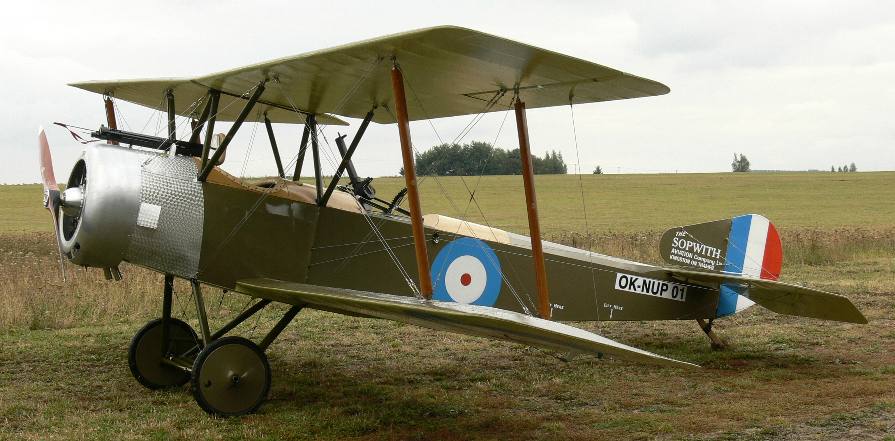
“The Sopwith Salamander” by Robert H. Rankin

Link - Posted by David on December 14, 2015 @ 6:00 am in

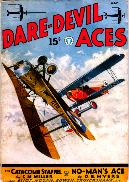
Frederick Blakeslee painted all the covers for the entire run of Dare-Devil Aces. And each of those covers had a story behind it. Although this looks like it should be in his new series of scrambled time covers, instead we get Robert H. Rankin, formerly a draughtsman for Fokker Aircraft Corp, telling the story of the last of the Sopwith war-time machines—The Sopwith Salamander—from the cover of the November 1935 number of Dare-Devil Aces!
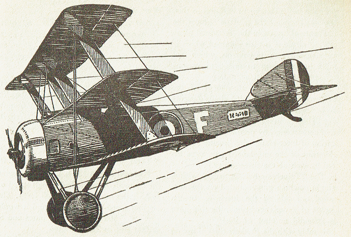
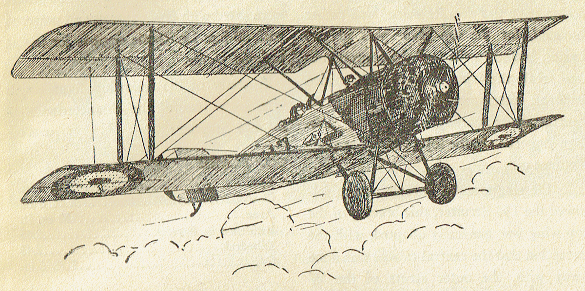
th_DDA_3511THE SALAMANDER, the last of the Sopwith war-time machines, was one of the most interesting and efficient types used in the World War. Although the design of the Salamander followed that of the earlier developed Sopwith Snipe, the plane was not intended for use as a scout or fighter—as were the Camel, Pup, Dolphin, and Snipe. It was designed primarily as a trench fighter, and in official circles it was known as the T.F.2.

The rudder of the Salamander was larger than those on the majority of the Sopwith designs. The pilot’s head, owing to the extremely deep fuselage and comparatively small wing gap, was on a level with the top plane, the center of which was partly slotted and partly cut away, to insure a better vision.

Due to the rather large diameter of the engine used, a B.R.2., the rectangularity of the fuselage was apparent toward the tail only, with the result that the fuselage was of a more circular cross-section than was the case in the other Sopwith ships.

Perhaps the mast interesting feature of the Salamander was the manner in which it was armored. Light steel plating formed the front of the fuselage from a point immediately in the rear of the engine, and extended to a point slightly to the rear of the cockpit. This armor, instead of being added to an existing fuselage frame, was a definite structual part of the frame work, and in itself formed the front portion of the fuselage. Thus, the armor plating served a structual, as well as a protective function.

Another variation from the usual Sopwith designs was incorporated in a tapering spine which served to taper off the pilot’s head and at the same time act as a head rest. This spine, being bulletproof, gave the pilot considerable protection against a rear attack.

The total weight of the armor in the Salamander totaled to some 650 pounds, and in addition to this weight, more than 2,000 rounds of ammunition was carried. In all, the ship weighed 2,945 pounds, as compared to the 1,959 pounds of the Dolphin, which was considered a rather heavy plane.

The following figures will give some idea of the performance and construction of the Salamander:


GENERAL SPECIFICATIONS
    Type Tractor Bi-plane
    Purpose Trench fighter
    Engine B.R.2, 230 h.p.
    Weights
        Loaded 2,945 lbs.
        Empty 1,844 lbs.
 
PERFORMANCE
    Speed (High—at 6,500 ft.) 123 m.p.h.
              (High—at 10,000 ft.) 117 m.p.h.
    Climb 10,000 ft. in 17 min.
    Landing speed 60 m.p.h.
    Ceiling 14,000 ft.
 
DIMENSIONS
    Length, over all 19 ft. 6 in.
    Stagger 1 ft. 5 in.
    Sweepback None
    Top Wing
        Span 31 ft 2⅝ in.
        Chord 5 ft.
        Area, not including ailerons 139 sq.ft.
        Incidence 1.8 deg.
        Dihedral 4.0 deg.
    Bottom Wing
        Span 30 ft. 2½ in.
        Chord 5 ft.
        Area, not including ailerons 123 sq.ft.
        Incidence 1.8 deg.
        Dihedral 4.0 deg.
 
AREAS
    Total wing area, not including ailerons
    Total wing, not inch ailerons 272 sq. ft.
    Tailplane 15 sq. ft.
    Elevators 11 sq. ft.
    Fin 2.75 sq. ft.
    Rudder 9 sq. ft.
    Total aileron area 51 sq. ft.


With the weights carried, the machine had a loading of 11 pounds per horse power, or 9.4 pounds per square foot.

As originally designed, the Salamander was armed with two fixed machine guns, but with its development into a general ground strafer, and later into a contact-patrol ship, the armament was increased, first to four guns, and later to six guns. In this later type there were two Lewis guns mounted on the top wing in such a manner that they could be easily drawn back and reloaded by the pilot from the cockpit.

Then, two Vickers were fixed on the top of the cowling, synchronized to fire through the propeller arc, while two Lewis guns, intended for trench strafing work were mounted on the bottom of the cockpit in such a way as to fire through the floor of the fuselage at an angle of about forty-five degrees.

The Salamander was passed by the experimental board of the Sopwith concern in April, 1918, but it was not until considerably later on in the year that the plane reached a production stage. Consequently few of them were in service over the lines.

In the short time that they were in action they showed such a performance record that it is quite probable, had the conflict lasted longer, the Salamander would have been one of the outstanding planes.

It is interesting to note, in connection with the Salamander, that the armored airplane has always been generally accepted as a logical step in the evolution of military planes by aeronautical engineers and designers. In actuality, however, there have been very few armored ships produced, and in fact, it was not until late in the war that any machines of the armored classification appeared.

For the most part, the greater number of the so-called armored planes produced were most inefficient, and in most instances the protective plating was added to the fuselage frame work of a regular pursuit or observation ship, with the result that the total weight of the machine was increased to a point where, powered with the engines then in use, they were sadly underpowered.

The Salamander, however, was designed from the first as an armored fighter, and inasmuch as the armor plating was made an integral part of the structural framework, the weight problem was done away with. This particular Sopwith offered a definite advance over the designs then in use, and it will be interesting to note in just what ways the modern armored pursuits will follow this pioneer model.

The Story Behind The Cover
“The Sopwith Salamander: The Story Behind The Cover” by Frederick Blakeslee
(November 1935, Dare-Devil Aces)

“The Sopwith Triplane” by Robert H. Rankin

Link - Posted by David on September 28, 2015 @ 6:00 am in

Frederick Blakeslee painted all the covers for the entire run of Dare-Devil Aces. And each of those covers had a story behind it. This time, we have more of the approach he used for the covers he painted for Battle Aces—telling us about the ship on cover. But, instead of Mr Blakeslee telling us about the ship on the cover, we have Mr. Robert H. Rankin, formerly a draughtsman for the Fokker Aircraft Corp telling the story of the Sopwith Triplane—featured on the cover of the July 1935 cover of Dare-Devil Aces. . . .

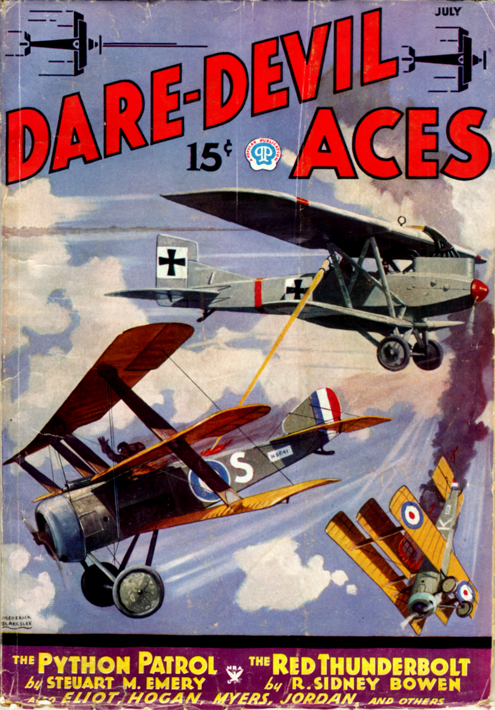
th_DDA_3507Editor’s Note: This month’s cover shows what would happen if a certain invention, had been perfected during the War. The rear-pit man in the all metal Junkers is operating a huge, highly magnified tense, so constructed as to concentrate a powerful percentage of the sun’s rays. When focused on the fabric covering of an airplane, this sunlight beam would cause a tiny burn. It is based on the same principle as that of lighting a fire by focusing sunlight on a small glass dial. The Allied ships on the cover are Sopwith triplanes.

The Sopwith Triplane
By ROBERT H. RANKIN
Formerly draughtsman, Fokker Aircraft Corporation

OF THE various Sopwith planes, all of which attained great fame, none is more interesting and characteristic than the Triplane—or as it was better known by the German and British pursuit pilots, the “Tripe” or “Tripe-hound.”

The Triplane was the ninth type produced by the Sopwith works, being accepted by the Experimental Board about four months after the Sopwith Pup. The principal object aimed at in the design of the Triplane was the attainment of an extra high degree of visibility, or in other words, the reduction to minimum of the pilot’s blind angle.

With his eyes on a level with the intermediate plane the pilot had practically an junrestricted arc of vision through some 120 degrees, while a section cut out of the intermediate wing enabled him to have a rather good view of the ground while landing the ship, the position of the cockpit being such that the bottom wing had no restricting effect on the vision.

The narrowness of the chord made possible by the use of three main planes also enabled the pilot to have an exceptional view upward and to either side—a most important consideration in any pursuit ship. Another object aimed at in the “Tripehound” was an increase in maneuverbility.

It will be seen that due to the narrow; chord the shifts in the center of pressure with varying angles of incidence is smaller than in a biplane, and consequently a much shorter fuselage can be used to suport the tail surfaces. In addition to this, the small span of the triplane reduces the moments of inertia in the horizontal plane and an airplane is thus obtained which is very sensitive to its controls, which fact adds to its ability to dodge to various strategic positions in a fight.

The factor of the movement of the center of pressure enabled single I-struts to be used instead of the usual pairs, one springing from each spar. This simplified construction by permitting a simplification of inter-plane wire bracing system. Ailerons of the unbalanced type were fitted to each of the three wings.

The “Tripehound” was armed with a single machine gun mounted on the forward top side of the fuselage. In the hands of experienced pilots the ship gave a splendid account of itself and coped favorably with the Fokkers then in use on the Western Front.

The dimensions of the Triplane follow:

Sweepback None
Stagger 1 ft. 6 in.
Dihedral (same for each wing) 2.5 degrees
Total wing area 231 sq.ft.
Length over all 18 ft. 10 in.
Overall span 26 ft. 6 in.
Wing span (same for each wing) 26 ft. 6 in.
Chord (same for each wing) 3 ft. 3in.
Wing areas—
    Top 84 sq. ft.
    Intermediate 72 sq. ft.
    Bottom 75 sq. ft.
    Gap 3 ft.
Areas—
    Aileron 34 sq. ft.
    Tail plane 14.0 sq. ft.
    Elevators 9.6 sq. ft.
    Total 23.6 sq.ft.
    Fin 2.5 sq. ft.
    Rudder 4.5 sq. ft.
    Total 6.5 sq. ft.


Powered with a 130 h.p. Clerget engine the Sopwith Triplane had a high speed of 112.5 miles an hour (at 6,500 feet). The landing speed was 35 m.p.h. and it would climb to 6,500 feet in 6.5 minutes and to 15,000 feet in 22.3 minutes.

The plane had a fuel capacity of 180 pounds and a flight range of 310 miles. The ceiling was 20,500 feet. The “Tripehound” weighed 1,103 pounds empty and 1,543 pounds loaded which made a loading of 6 pounds per square foot or 12.4 pounds per horse power.

Although judged by present standards the Triplane was low-powered and rather slow, its speed, ease of handling and general performance were outstanding at the time of its introduction into the Royal Flying Corps.

The Story Behind The Cover
“The Sopwith Triplane” by Frederick Blakeslee (July 1935, Dare-Devil Aces)
“The Fokker Triplane” By Robert H. Rankin

Link - Posted by David on September 21, 2015 @ 6:00 am in

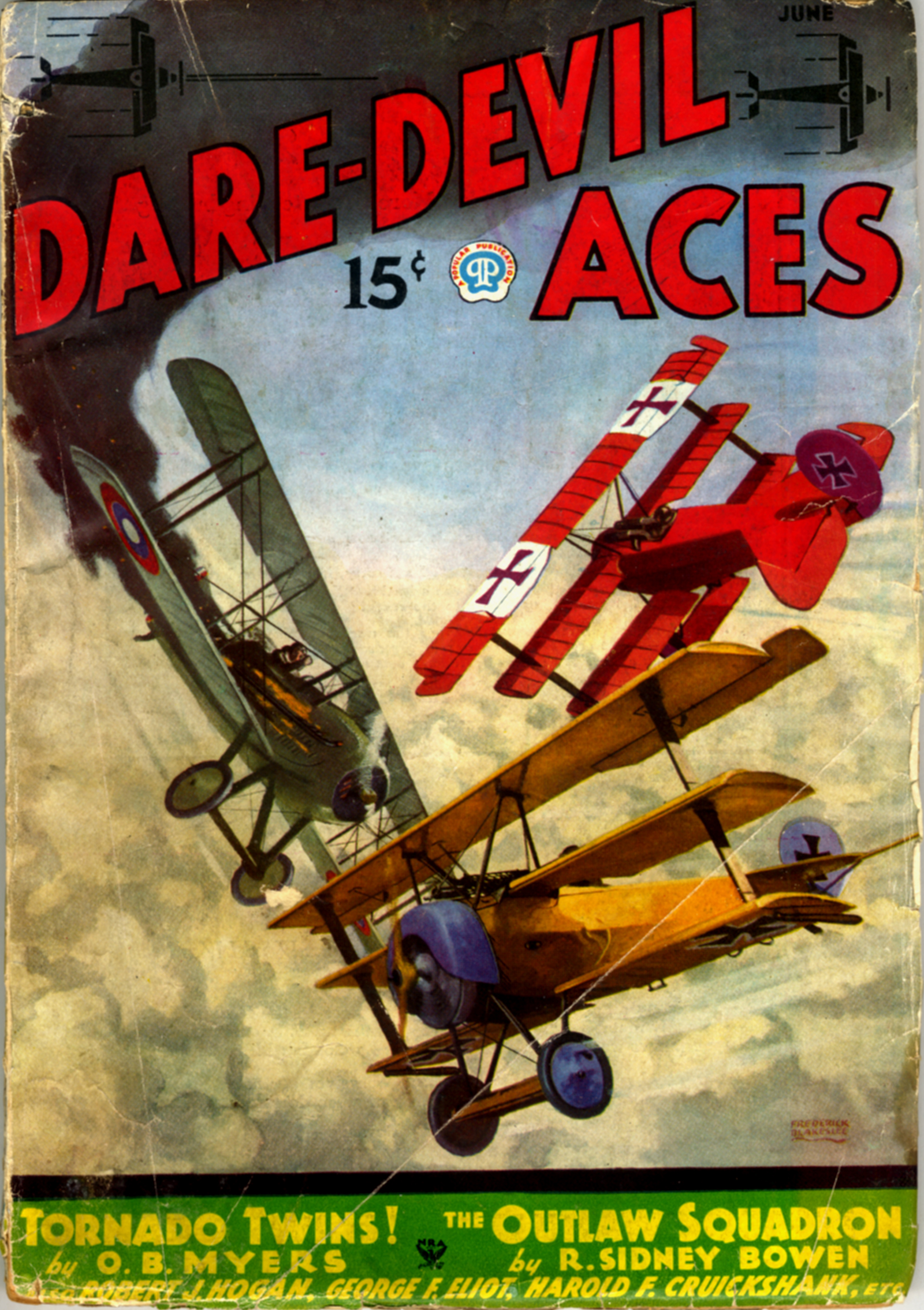
Frederick Blakeslee painted all the covers for the entire run of Dare-Devil Aces. And each of those covers had a story behind it. This time, we have more of the approach he used for the covers he painted for Battle Aces—telling us about the ship on cover. But, instead of Mr Blakeslee telling us about the ship on the cover, we have Mr. Robert H. Rankin, formerly a draughtsman for the Fokker Aircraft Corp telling the story of the most recognized plane of the era—the Fokker Triplane—featured on the cover of the June 1935 cover of Dare-Devil Aces. . . .

th_DDA_3506AFTER one look at the cover this month you would probably think that the American and German pilot were doomed. However, both escaped, the American with minor burns and the German with a bad fright.
  As a matter of fact, the fire on the Spad was not quite as bad as we have shown; just bad enough to make the pilot think that he was due for an awful death. He decided to crash one of the Fokker tripes, bringing it down with him. But the pilot of the Fokker got ont of the way just in the nick of time.
  The American discovered in that dive that if he side-slipped the blast of wind would keep the fire away from the cockpit. He managed to reach the ground by side-slipping. As he later said—”Given my choice of crashing or being burned to a cinder, I’ll crash every time.” And crash he did.

Now let’s hear from an expert the inside dope on the Fokker triplane.

The Fokker Triplane
By ROBERT H. RANKIN
Formerly Draftsman, Fokker Aircraft Corporation

DURING the early part of the year 1916 the German High Command realized that the war had developed into a bitter struggle which would be prolonged much longer than had at first been expected.

With this fact in mind, Germany at once redoubled her efforts to gain undisputed supremacy of the skies and Anthony Fokker was asked to design and produce a new combat ship which would enable her to gain the upper hand. Fokker set to work at once and in the early fall of 1916 this plane was placed in the hands of the fighting pilots. It was the Fokker D.R.-I, or as it was perhaps better known, the Fokker triplane.

At first the performance of the triplane was not viewed seriously by the Allies. But within a short time they learned to have a high regard for the new Fokker pursuit. Although this unique ship was slower than the Nieuports, Sopwiths and Spads, its ability to climb and maneuver gave it a decided advantage over any ship then in use and the series of impressive victories for which it was responsible gave the entire world notice that it was a most important factor in aerial warfare.

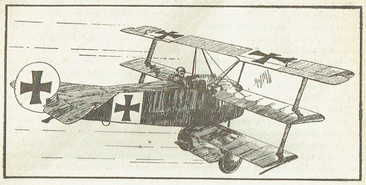
In general outline the Fokker D.R.-I was of the orthodox triplane type. However, unlike the Sopwith triplane the span of the wings were unequal.

The span for the top wing was 23 feet, 7 inches, the span for the middle wing was 20 feet, 6 inches, while the span of the bottom wing was 18 feet, 9 inches. The chord was the same for all three wings. The top wing alone was provided with ailerons, and these were of the balanced type.

One of the outstanding features of the Fokker was the wing spar construction. The main point of interest is that the twin spars were built up of two box section tapering spars, these being joined by transverse plywood. The front and rear shear strength of this built-up member was supplied by one right and one left plywood bulkhead in each wing.

Structurally the main wing frame could be regarded as consisting of three pairs of cantilevers tied by pseudo-struts near the wing-tips. The function of this structure was to distribute the load evenly from wing to wing.

The use of the triplane design gave the advantage of a larger ratio of lifting power. Of course, there was some increase in head resistance caused by the use of the extra set of inter-plane struts. But by bracing the wings internally, Fokker eliminated all brace wires, thus reducing the total head resistance to some extent.

It is interesting to note in connection with this that Fokker was the first designer to completely do away with inter-plane bracing.

The Story Behind The Cover
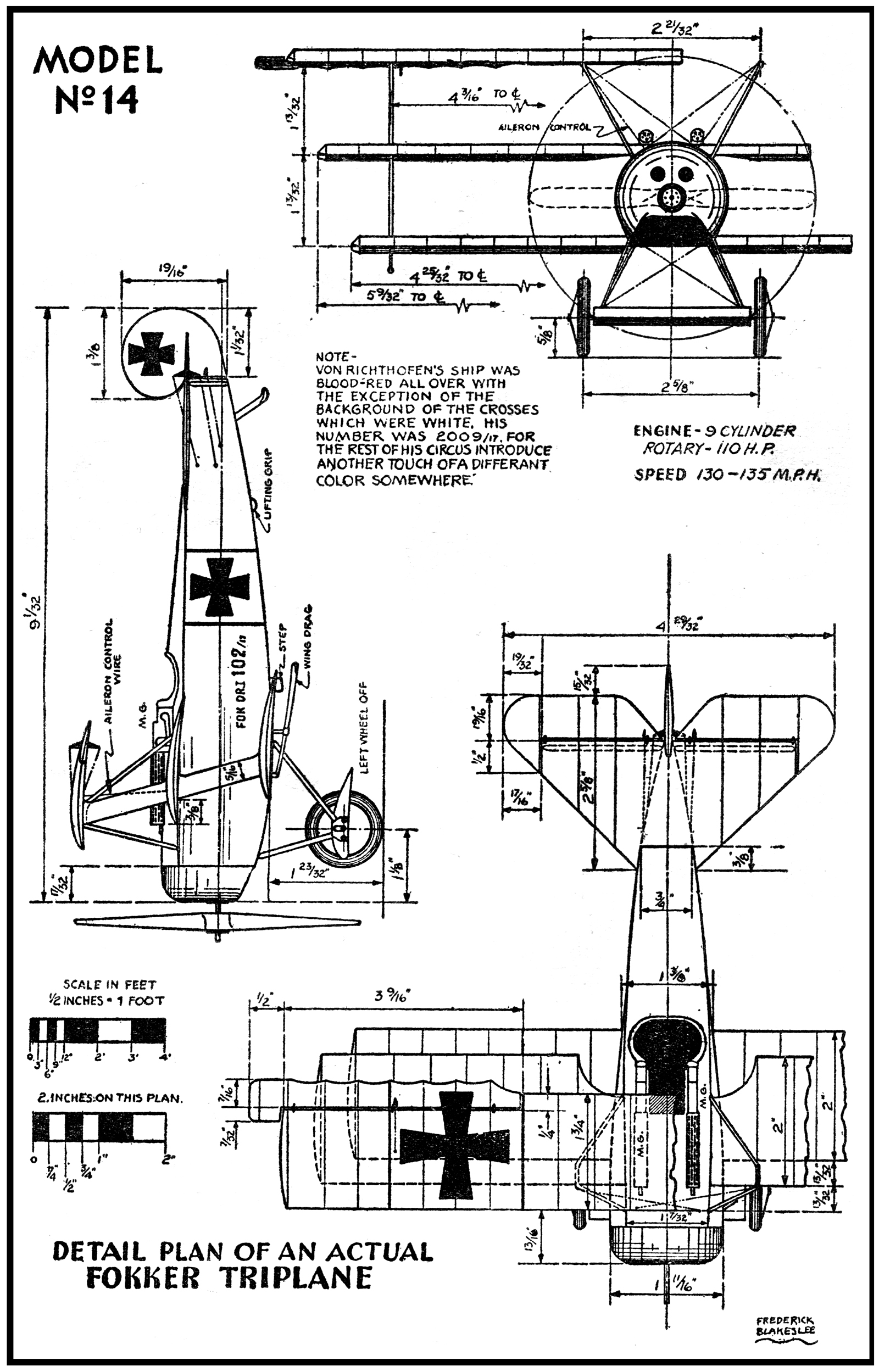
“Model No.14 – Fokker Triplane” by Frederick Blakeslee (January 1934, Battle Birds)

The fuselage of the triplane was built up of welded tubular steel and was covered with linen fabric. It was rather well streamlined, and like most of the Fokker war-time designs it compared closely to modern aeronautical practice.

The empennage or tail of the ship was a fabric covered steel tubing framework. There was no vertical fin, there being only the characteristic Fokker rudder. The tail plane or stabilizer was comparatively large and was fitted with the usual type elevators.

The landing gear axle was inclosed by a wing, a feature which was incorporated on all of the later Fokker fighting models. This wing was two pieces and these were attached to a central casting which housed the shock absorbing agents and the axle. The covering for this wing was plywood.

The triplane or D.R.-I was equipped with a 110 h.p. 9 cylinder Oberursel rotary motor. This motor was mounted on a plate which was stamped from sheet steel. The plate was attached, of course, to the front ends of the fuselage longerons.

For armament the plane was fitted with twin Spandau machine guns, these being mounted on the top side of the fuselage directly in front of the cockpit. Directly behind the engine was the synchronizing gear for the guns, and behind this gear was located the fuel tank. This tank was of a rather small capacity and as a result the flight range of the machine was greatly limited.

The triplane answered very well to the controls and as far as climb and general maneuverability are concerned it was equaled by but very few of the later war time designs.

German pilots have told the writer that they were greatly impressed with the ship and if the speed of the plane could have been increased they would have preferred it to any other plane, with the possible exception of the D-VTI. Certainly it was the choice of many of the German pilots.

The great von Richthofen, who could select any ship he desired, favored it above them all; and his series of victories indicate the famous flyer made no mistake in his choice of a pursuit.

The Story Behind The Cover
“The Fokker Triplane” by Frederick Blakeslee (June 1935, Dare-Devil Aces)


Mr. Blakeslee covered the Fokker Triplane himself with the story of the great von Richthofen last flight for the cover of the March 1932 number of Battle Aces.

“Sopwith 1½ Strutter” by Robert H. Rankin

Link - Posted by David on September 14, 2015 @ 6:00 am in

Frederick Blakeslee painted all the covers for the entire run of Dare-Devil Aces. And each of those covers had a story behind it. This time, we have more of the approach he used for the covers he painted for Battle Aces—telling us about the ship on cover. But, instead of Mr Blakeslee telling us about the ship on the cover, we have Mr. Robert H. Rankin, formerly a draughtsman for the Fokker Aircraft Corp telling the story of the Sopwith 1½ Strutter on the cover of the May 1935 cover of Dare-Devil Aces. . . .

th_DDA_3505
Editor’s Note: This is a surprise cover. In painting it, Frederick Blakeslee attempted to tell no story, but simply painted a ship for your collection. The color and every detail on the ship is exactly as it is on the original. We are very anxious to know how you like this cover. Write to Frederick Blakeslee in care of this magazine and tell him what type of cover you like best.

Sopwith 1½ Strutter
by ROBERT H. RANKIN
Formerly Draughtsman, Fokker Aircraft Corporation

WITH the exception of Fokkers, the Sopwiths were in all probability the best-known fighting ships used during the World War. The Sopwith Camels did more to repulse the German attempts at aerial supremacy than any other type or make of plane, while the Sopwith Pups and Triplanes made themselves almost equally as famous.

Although not as well-known as the other Sopwith models, the 1½ Strutter has a definite claim to historical distinction, not only because it was a great fighter, but because it was the first British plane to be fitted with a gun synchronized to shoot through the propeller.

The Sopwith-Kauper synchronization gear which made this possible was developed at the Sopwith factory and was as much a product of that firm as was the ship to which it was fitted.

The 1½ Strutter was originally designed as a high-performance two-seater fighter powered with the 100 h.p. Clerget engine. As such it gave a very good account of its self, showing an excellent performance and a decided ease of maneuverability.

In view of its worth as a fighter, many 1½ Strutters were built to the order of the governments of Roumania, Russia, Belgium, and the United States. In addition to this, the French government, under license, built more than 4,500 of these machines.

Structurally the 1½ Strutter was interesting in several ways. The wing bracing, which gave the ship its name, was rather unusual, for the top plane was in two halves, bolted to the top of a central cabane, while the wing spars were provided with an extra support in the shape of shorter struts running from the top fuselage longerons to the top plane spars some distance out.

In the single-seater pursuits which followed the 1½ Strutter, this bracing of the top wing was generally adopted, with the exception that the central cabane was done away with, the outer struts of the W formation having a slightly less pronounced slope, and supporting a separate top wing centersection.

Aerodynamically the machine is of interest because of the air-brakes with which it was fitted. These were in the form of adjustable flaps in the trailing edge of the lower wings. These flaps could be rotated by the pilot until they were normal to the wind, thus helping to pull the plane up as it was about to land.

Another innovation incorporated in the 1½ Strutter was the trimming gear by means of which the angle of incidence of the tail plane could be altered in flight. This allowed the tail to be adjusted for speed, climbing, etc.

Although designed originally to be used as a two-seater fighter only, the 1½ Strutter was later successfully adopted as a single-seater bomber, and as such it was used in bombing such German towns as Essen, Munich, and Frankfort. For bombing service the machine was equipped with the 130 h.p. Clerget.

Later this higher-powered engine was used in the standard two-seater fighters. After the war a number of these fighters were fitted with dual controls and powered with 80 h.p. Le Rhone engines for use as training planes.

A study of the following figures will give some idea of the characteristics of the 1½ Strutter:

TOP PLANE
   
Span 33 ft. 6 in.
Chord S ft. 6 in.
Area 183 sq. ft.
Incidence in degrees 2.45
Dihedral 2.45
Gap 5 ft. 5 in.
   
BOTTOM PLANE
   
All dimensions the same as for the top plane.
   
GENERAL DIMENSIONS
   
Total wing area 373 sq. ft.
Length over all 25 ft. 4 in.
Stagger 2 ft. 0 in.
Sweepback 0 ft. 0 in.
Aileron area 52 sq. ft.
Tail plane area 35.5 sq. ft.
Elevator area 21.5 sq. ft.
Fin area 3.5 sq. ft.
Rudder area 7.25 sq. ft.


Powered with the 110 h.p. Clerget engine, the two-seater fighter weighed 1,281 pounds empty, had a high speed of 130 m.p.h. and climbed 6,500 feet in 10½ minutes. The ceiling was 16,000 feet, the military load 160 pounds, and the landing speed 35 m.p.h. In addition to the fixed gun, the fighter carried a Scarfe ring and gun for the use of the man in the rear pit.

As a bomber, powered with the 130 h.p. Clerget, the ship weighed 1,316 pounds empty, showed a high speed of 102 m.p.h., and climbed to 6,500 feet in 12.7 minutes. The ceiling was 13,000 feet, the military load was 344 pounds, and the landing speed 35 m.p.h.

The Story Behind The Cover
“Sopwith 1½ Strutter” by Frederick Blakeslee (May 1935, Dare-Devil Aces)

“The Fokker D-VII” by Robert H. Rankin

Link - Posted by David on July 27, 2015 @ 6:00 am in

Frederick Blakeslee painted all the covers for the entire run of Dare-Devil Aces. And each of those covers had a story behind it. This time, we have more of the approach he used for the covers he painted for Battle Aces—telling us about the ship on cover. But, instead of Mr Blakeslee telling us about the ship on the cover, we have Mr. Robert H. Rankin, formerly a draughtsman for the Fokker Aircraft Corp telling the story of the Fokker D-VII on the cover of the February 1935 cover of Dare-Devil Aces. . . .

th_DDA_3502The contraption shown on the cover was supposed to have been invented just after our entry into the war. The idea was for a bomber to drop the net and then the combat ships were to lure the enemy into it, or else the combat ship was to carry the net itself. The story goes that the inventor offered it to the U.S. government, then to France and England and finally into German hands. (A similar device was employed in the Sky Devil story “The Haunted Fokker” (Dare-Devil Ace, April 1933))

Now let’s review the history of the Fokker D-VII, written by an authority on the subject.

THE FOKKER D-VII
by ROBERT H. RANKIN
Formerly Draughtsman, Fokker Aircraft Corp.

TO ANY one familiar with the fighting planes developed during the World War the Fokker D-VII is outstanding. It was superior to any other plane used by Germany and it was certainly the equal of any machine used by the Allies. Using the D-VII the German pilots were able to hold their own against a much larger force of Allied aircraft, and so great did the fear of these planes become that it was definitely stated in terms of the Armistice that all Fokker planes should be destroyed.

The D-VII was the result of the gradual development of the earlier Fokker Fighters. When it was found that the 110 H.P. Le Rhone powered Nieuport easily outmoded the 80 H.P. Gnome powered Fokker the design of the Fokker tri-plane was completed.

The triplane enabled the German pilots to gain a series of impressive victories and it was used by the great von Richthofen in many of his aerial duels. Although the speed of this plane was comparatively slow, its decided ease of maneuverability more than made up for the disadvantage.

But its flight range was limited by a small gasoline capacity and Allied pilots found that the best way to escape it was to out-distance it.

As it became apparent that the fighting planes of the Allies, and in particular the Sopwith Camels and Spads, were giving them the advantages of speed and flight range the design of the D Series Fokkers was started. The first of these was the D-I, a bi-plane powered with a 120 H.P. Mercedes, and like the rest of the series it was fast and efficient.

About this time the Albatros works (Albatros Werke) began production of the D Series Albatros machines. The Albatros D-II proved itself superior to the Fokker D-I and by 1917 the later developed D-III had surplanted the Fokkers at the Front. This Albatros was powered with a 175 H.P. Mercedes, weighed 1,470 lbs. and carried a useful load of 297 lbs.

These D Series Albatros planes were a bi-plane design, having a small lower wing (made of a single spar) connected to a larger upper wing with a V strut. Any combat advantages which the Albatros offered were offset by the fact that the plane was structurally weak and the wings could not stand torsions. Consequently, when fighting the Albatros, Allied pilots had but to put their planes into a steep dive to be safe.

Many German airmen were killed when their planes went to pieces in mid-air; the celebrated Captain Boelke met death when the wings of his Albatros pulled off while he was flying over his own lines. Several pilots deliberately wrecked their machines rather than take them into the air.

The father of the D-VII was a bi-plane of somewhat radical appearance. Its fabric-covered fuselage was made of wood covered welded tubing, making a clean and decidedly streamlined job. The wings were built up of wood in much the same manner as were the wings of the later Fokker commercial types.

Although this plane offered every advantage and was years ahead of its time in many ways it was refused by the German High Command. Realizing that little satisfaction could be had from the German government (politics meaning more to them than efficient fighting equipment) Mr. Fokker managed to contact the important pilots. He found that they were not satisfied with the planes and materials furnished them and they desired to select their own equipment.

After some difficulty and much red tape an open competition of the leading makes of military planes was held. For this competition Fokker redesigned his bi-plane and the D-VII was born.

The D-VII was characterized by its cantilever wings (made up of box spars). No wires or external braces were used and the wings were joined together at the tips with a single strut. The fuselage was of a rectangular cross section which feature made for simplified manufacturing and quantity production. By streamlining the landing gear axle with a tiny wing, speed was added to the plane.

The D-VII fast became a favorite of the pilots. Although the Rumpler climbed faster, it handled very badly, especially on the turns. So great was the demand for the new Fokker that the factories making other planes were required to stop production of their own types and concentrate on the building of the D-VIIs.

The following figures give an insight into the construction and performance of the plane.

Wing curve Fokker varying
Sweepback None
Dihedral, upper wing 2°
Dihedral, lower wing 1° 20′
Stagger 2′ 1″
Total wing area, including ailerons 236 sq. ft.
 
Upper plane—
  Span 27′ 5½”
  Chord 5′ 3″
  Area, with ailerons 145 sq. ft
 
Lower plane—
  Span 22′ 11¼”
  Chord 3′ 11¼”
  Area 91 sq. ft.
  Incidence 1 to 1.5 degrees
  Gap 4′ 6¼”
 
Fuselage—
  Max. cross section shape Rectangular
  Max. cross section area 9.35 sq. ft.
  Max. cross section dimension 3′ 9½” by 2′ 5½”
 
General Dimensions—
  Overall span 27′ by 5½”
  Length 23′
  Height 9′ 3″
 
The weight of plane (empty, including water) 1,867 pounds
The weight of plane loaded 2,462 pounds

The endurance of the Fokker D-VII is, full throttle at 10,000 feet (including climb) 2 hrs. 13 minutes.

Minimum speed of the D-VII at sea level (lowest throttle) is 62 miles per hour.

The Story Behind The Cover
“The Fokker D-VII” by Frederick Blakeslee (February 1935, Dare-Devil Aces)


Mr. Blakeslee covered the Fokker D-VII himself with the story of Billy Bishop for the cover of the February 1932 number of Battle Aces.